Really? That's pretty interesting. I can't decide if the functionality of a real remote would be handy or annoying. I kind of like the dial setup. I can keep one hand on the tiller and one on the speed dial.A step further would be to use the RC controller approach for fully remote control. You just hang the controller on a lanyard or something. Pretty easy to do and lots of youtube vids on how to do it.
You are using an out of date browser. It may not display this or other websites correctly.
You should upgrade or use an alternative browser.
You should upgrade or use an alternative browser.
PWM
- Thread starter Ronbow
- Start date
I have a remote control with my Minn Kota on my boat and i think it is the easiest way to control your direction and speed, I would be lost without it. It has a lanyard and also a belt clip.Really? That's pretty interesting. I can't decide if the functionality of a real remote would be handy or annoying. I kind of like the dial setup. I can keep one hand on the tiller and one on the speed dial.
As I understand it, there is no savings at full bore. Only the lower speeds.Question: is there any battery saving advantage to running a pwm versus no pwm if you’re running at full speed? I would think it only comes when you’re running at lower speeds but just want to confirm...
As I understand it, there is no savings at full bore. Only the lower speeds.
That's correct. The numbers in blue in the table below - speed, thrust and amp draw - are published by Minn Kota. Being the bored engineer, I added in the % and efficiency columns. The real benefit of the PWM controllers is at the lower speeds where the 5 speed controller is comparatively very inefficient.
Ken

Help me out here... Is this showing a standard trolling motor or a PWM? Not sure Endura C2 is considered a PWM? I think the Traxxis is though.That's correct. The numbers in blue in the table below - speed, thrust and amp draw - are published by Minn Kota. Being the bored engineer, I added in the % and efficiency columns. The real benefit of the PWM controllers is at the lower speeds where the 5 speed controller is comparatively very inefficient.
Ken
View attachment 23732
I also saw this chart and if true wondered why we are all building PWM controllers other than the variable speed feature.That's correct. The numbers in blue in the table below - speed, thrust and amp draw - are published by Minn Kota. Being the bored engineer, I added in the % and efficiency columns. The real benefit of the PWM controllers is at the lower speeds where the 5 speed controller is comparatively very inefficient.
Ken
View attachment 23732
This is kind of a makeshift setup but it shows even less amperage draw.
Last edited:
I also saw this chart and if true wondered why we are all building PWM controllers other than the variable speed feature.
This is kind of a makeshift setup but it shows even less amperage draw.
This is a guess on my part, Dean, but I doubt the motor in a bucket duplicates the energy required to push a boat forward althought MinnKota's chart doesn't say how they determined draw.
Probably true but I was under the impression that the amperage draw would be the same on all speeds, hence the rationale for a PWM.This is a guess on my part, Dean, but I doubt the motor in a bucket duplicates the energy required to push a boat forward
Last edited:
That is a standard motor. Endura C2 is not a PWM motor.Help me out here... Is this showing a standard trolling motor or a PWM? Not sure Endura C2 is considered a PWM? I think the Traxxis is though.
Right, so wouldn't we need a similar table for a pwm to compare?That is a standard motor. Endura C2 is not a PWM motor.
Also from Minn Kota which seems to kinda negate the credibility of the numbers on the other chart.
Due to the many variables when boating (including wind, waves, current, battery condition, etc.) we are unable to specify the amp draw at any speeds other than max power. The motor is only able to draw up to a specified amperage. You can reference the Conductor Gauge and Circuit Breaker Sizing Table in the link below for the maximum amp draw for your motor.
Due to the many variables when boating (including wind, waves, current, battery condition, etc.) we are unable to specify the amp draw at any speeds other than max power. The motor is only able to draw up to a specified amperage. You can reference the Conductor Gauge and Circuit Breaker Sizing Table in the link below for the maximum amp draw for your motor.
An amperage comparison at 20, 40, 60, 80, and 100% to speeds 1-5 would be interesting.Right, so wouldn't we need a similar table for a pwm to compare?
Since I have the parts I'll still finish building mine for the variable speed as the lowest setting still trolls my boat too fast.
The chart above is only for the conventional 5 speed Endura C2 motor using the stock Minn Kota controller. Keep in mind that my "efficiency" column is only a simplistic ratio of the thrust vs amperage columns. This is basically just a baseline of the stock motor/controller. The guy in the YouTube video that Buzzy linked to basically got identical amperage numbers for speeds 1, 2, and 3 that are in my table.
The unstated assumption is that a PWM would have a more linear 1:1 characteristic regarding thrust vs battery power used. Setting the PWM controller to 10% should provide close to 10% of the maximum thrust of the motor.
Electrical is not one of my strengths, but from my understanding of PWM, Dean's statement is correct that actual amperage of each PWM pulse is the same (e.g. 30 amps for the Endura C2) at all speeds. My knowledge of PWM principles is pretty much limited to the info below.
Because of the pulse nature of PWM, I'm not sure what amperage a multi-meter would show for a PWM signal? In order to accurately compare a PWM controller to the Minn Kota 5 speed controller I think you need to look at amps used during a period of time for both controllers.
*********************************************

The unstated assumption is that a PWM would have a more linear 1:1 characteristic regarding thrust vs battery power used. Setting the PWM controller to 10% should provide close to 10% of the maximum thrust of the motor.
Probably true but I was under the impression that the amperage draw would be the same on all speeds, hence the rationale for a PWM.
Electrical is not one of my strengths, but from my understanding of PWM, Dean's statement is correct that actual amperage of each PWM pulse is the same (e.g. 30 amps for the Endura C2) at all speeds. My knowledge of PWM principles is pretty much limited to the info below.
Because of the pulse nature of PWM, I'm not sure what amperage a multi-meter would show for a PWM signal? In order to accurately compare a PWM controller to the Minn Kota 5 speed controller I think you need to look at amps used during a period of time for both controllers.
*********************************************
I finally got around to ordering the additional parts needed to build my PWM.
Below are a few shots of the finished product installed on my Spring Creek pram.
I still need to do a little cleanup in the battery box area but I have an inline fuse and "Anderson style" connectors that allow me to bipass the PWM should it fail. (BTW, these red connectors were supposed to mate with the true Anderson's but don't.)

These are 10 gauge ring connectors on 10 gauge silicon wire but I had to slightly file the sides of the ring so they would fit.

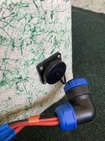
I looked long and hard for a 4 pin, 10 gauge plug in connector and finally found this one. The 90 degree angle was a real bonus for my application.

The finished product attached to the battery box/seat pedestal with HD Velcro...
I hope the adhesive will hold up to the up with this upcoming heat.

The best part is that it actually works.
.jpg")
Below are a few shots of the finished product installed on my Spring Creek pram.
I still need to do a little cleanup in the battery box area but I have an inline fuse and "Anderson style" connectors that allow me to bipass the PWM should it fail. (BTW, these red connectors were supposed to mate with the true Anderson's but don't.)
These are 10 gauge ring connectors on 10 gauge silicon wire but I had to slightly file the sides of the ring so they would fit.
I looked long and hard for a 4 pin, 10 gauge plug in connector and finally found this one. The 90 degree angle was a real bonus for my application.
The finished product attached to the battery box/seat pedestal with HD Velcro...
I hope the adhesive will hold up to the up with this upcoming heat.
The best part is that it actually works.
Attachments
Last edited:
Let this coming heat wave pass and time for the real test, from the launch to the east end of A Lake and back again! Hold onto that rod this time. ;-)I finally got around to ordering the additional parts needed to build my PWM.
Below are a few shots of the finished product installed on my Spring Creek pram.
I still need to do a little cleanup in the battery box area but I have an inline fuse and "Anderson style" connectors that allow me to bipass the PWM should it fail. (BTW, these red connectors were supposed to mate with the true Anderson's but don't.)
View attachment 24312
These are 10 gauge ring connectors on 10 gauge silicon wire but I had to slightly file the sides of the ring so they would fit.
View attachment 24313
I looked long and hard for a 4 pin, 10 gauge plug in connector and finally found this one. The 90 degree angle was a real bonus for my application.
View attachment 24314
The finished product attached to the battery box/seat pedestal with HD Velcro...
I hope the adhesive will hold up to the up with this upcoming heat.
View attachment 24315
The best part is that it actually works.
View attachment 24321
I finally got on the water last Friday and the PWM worked great. With my Spring Creek pram I ran from 22-28%, depending on breeze variations, for a slow troll. I felt the unit numerous times and didn't detect any heat at all. The best part was that after quite a bit of run time on my C2 Minnkota the 35 AH battery still shows full using my Minnkota tester.
.jpg")
Last edited: